JeeNodes

Description

Issues around HAHNode and JeeNodes

Forums

It my turn to ask for help  :)

I've got this 23,000 litre tank (~5060 gal) out the back of my place which harvests rain water which we can use to run the entire house from.  During summer it does run low so we switch back to mains water.

My projects is to measure how much water is in the tank, so can see how much we are using and how much rain is falling to fill it, and to know when to swtich over to mains before we get to low.

As the tank is sealed at the top, with mesh to prevent mosquitos from getting inside, there is no physicall access to the inside the tank, which means ultrasonic measurement is out. I really wanted to play with that too.  Instead I was thinking of using a Pressure transducer.

There are two ways I could do this.  Wet or Dry.

A dry approach would use a BMP085 which I already happen to have, sealed into the end of a hose.  This hose would then be suspended in the air at a height greater than the water in the tank.   The other end attached to a tap (pre pump) as the water rises the AIR pressure increases/decreases and I can measure this to determine water volume as in inverse relationship.

The Wet approach is to get a pressure transducer which is simply fitted onto the end of a tap.  It works the same way but measures the water pressure directly.  I'm more inclined to do this as it feels easier.

A column of water 2.31 feet tall creates 1 pound per square inch (psi) of pressure and my tank is 2.6m high (8.53 feet) which is about 3.6 PSI when full.   So I'm thinking a 0-5 PSI water pressure transducer would do the job.

http://www.ebay.com.au/itm/100PSI-Pressure-Transducer-or-Sender-for-Oil…
But of course not 100psi I've never get a reading !

What do we think?  Sounds feasable?

Brett

Forums

I had to tweak the roomnode2 sketch a little but heres the code for the DHT22 Temp and Humidty Sensor which has slight improvments on the DHT11

Dont forget to get a decent DHT22 lib for Arduino, i used Ben Adams - https://github.com/nethoncho/Arduino-DHT22

DHT11

  • Ultra low cost
  • 3 to 5V power and I/O
  • 2.5mA max current use during conversion (while requesting data)
  • Good for 20-80% humidity readings with 5% accuracy
  • Good for 0-50°C temperature readings ±2°C accuracy
  • No more than 1 Hz sampling rate (once every second)
  • Body size 15.5mm x 12mm x 5.5mm
  • 4 pins with 0.1" spacing

DHT22

  • Low cost
  • 3 to 5V power and I/O
  • 2.5mA max current use during conversion (while requesting data)
  • Good for 0-100% humidity readings with 2-5% accuracy
  • Good for -40 to 125°C temperature readings ±0.5°C accuracy
  • No more than 0.5 Hz sampling rate (once every 2 seconds)
  • Body size 15.1mm x 25mm x 7.7mm
  • 4 pins with 0.1" spacing


Forums

Work in process still but i thought i would chuck an idea around and see if anyone has any further suggestions


I have a vaillant ecotec plus 831 boiler which uses the semi-propiertry Ebus protocol to communicate beetween the room stat and boiler

theres various homebrew ebus interfaces around on the net that allow your to send packets via TTL levels or via a 232 Level convertor

these typically connect to ebus 2 wire serial interface and communicate using the protocol spec

initial idea is to use a modified basenode and HAHCentral to communicate with a remote roomnode connected via TX & RX pins into the EBUS module which inturn is connected to the boiler

we could then send xap packets using the Serial.Comms class generated by a custom lua

xap-header
{
v=12
hop=1
uid=FF00DD00
class=serial.comms
source=dbzoo.test.demo
target=dbzoo.livebox.serial
}
Serial.Send
{
port=/dev/ttyUSB0
data=Hello world!
}

just an initial idea so far, not really sure if this is the best method of approach - suggestions welcome

Andrew

Edit - a second option (more cost effective) - http://www.ebay.co.uk/itm/Arduino-Bluetooth-Wireless-Serial-Port-Module-RS232-TTL-Tranceiver-Upto-30-Feet-/321105282804?_trksid=p2054897.l4275

i could use the serial schema to communicate with the transmitter module
Forums

I have a jeenode on top of the compost bin - the signal is very weak.  So dug around and found someone was using the software rf12_getRSSI function to create a crude 7 level signal strength.  I have got so far with my new found knowledge - able to get the following:
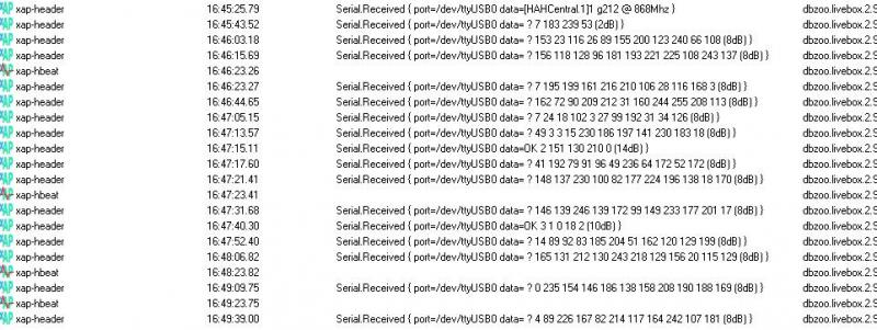
The data has been truncated from 20 to 10 items 'cos I am not really interested in all the junk.

Clearely the 8,10,14db is wrong - it is simply reporting the RSSI and not translating it - and this is where i have the problem.

First of all I take no credit for the idea - it is simply hacked from http://forum.jeelabs.net/node/1470.html

Without knowing how to use the version control properly or how to do patching I took the following approach:

1) I got a new version of RF12.cpp, RF12.h, RF12sio.cpp and RF12sio.h from https://github.com/jcw/jeelib/tree/rf12mods

(didn't know if I needed the last two files ) and simply poked them into the Arduino library (getting a red exclamation mark for my troubles)

2) Hacked the patch from the above forum link

for (byte i = 0; i < n; ++i) {

Serial.print(' ');

Serial.print((int) rf12_data[i]);

}

Serial.print(" (");

Serial.print(rf12_getRSSI(), DEC);

Serial.println("dB)");

into HAHcentral from

http://livebox-hah.googlecode.com/svn/trunk/userapps/arduino/HAHCentral/ which I believe is the 

source for HAHCentral_nocfg.cpp.hex

3) It compiled much to my surprise and the result is above.  I now  use Arduino ERW 1.0.5 because that shows me where

the hex path is and I can upload the new sketch via the livebox without turning it all off.

The problem is that I would like to try and use the code from his patch which would seem to go into RF12.cpp

// return signal strength calculated out of DRSSI bit
+int8_t rf12_getRSSI() {
+    if (! drssi & B1000)
+        return 0;
+    
+    const int8_t table[] = {-106, -100, -94, -88, -82, -76, -70};
+    return table[drssi & B111];
This will translate to a range from -70dB to -106 dB which is right.
I can't find out how to edit RF12.h without injecting loads of <CR><LF> which the compiler doesn't like.  Arduino 1.0.3 
won't edit this file type.

Any ideas?  Will this approach work? I'm a bit worried about the B1000 stuff whatever that is!
I think having signal strength is useful to help diagnose difficult path tranmission cases - I can work with the 1 to 7 levels reported but would like to make it look right - who knows it may get incorporated and I can get rid of my exclamation marks.

Regards

Kim 
Forums

So now I want to measure humidity in the house using a DHT11 delivered promptly from the shop.

The Jeenode Integration page refers to "The RoomNode2 sketch will also support the DHT11 sensor which is a drop in replacement for the DS18B20 and adds temperature and humidity; with change in the code to select this device instead."  Looking at the source for roomnode2.hex at http://livebox-hah.googlecode.com/svn/trunk/userapps/arduino/roomNode2/roomNode2.ino it looks as though DHT11 is already selected.  But it also says that "SHT11, ONE_WIRE and DHT11 are mutually exclusive." and since my temp sensor works when plugged in - I assume that #define ONE_WIRE_PIN 4 is active instead.

So ... I would like to try and compile my own change - and have started looking at WinAVR and other stuff.  Could someone advise me on the best (free) software to use.

Regards

Kim 

p.s.  I have already changed my Jeenode applet section to the following in readiness:

-- Keyed by NODE ID

local nodes = {

   [2] = RoomNode{base="dbzoo.livebox.2.jeenode:test", 

                  endpoints={temp=1,light=1,lobat=1,moved=1,humi=1}, ttl=360},


   [3] = BoilerNode{base="dbzoo.livebox.2.jeenode:util",

                  endpoints={temp=1,light=1,lobat=1,moved=1}, ttl=360},


   [4] = BoilerNodeTwin{base="dbzoo.livebox.2.jeenode:test2", 

                  endpoints={temp=1,light=1,lobat=1,moved=1,temp2=1}, ttl=360},

Forums

Hi,

I tried almost everything, but my jeenodes do not work.

In the attachment you can find my applets, they are quite similar to the given examples here.

My problem so far:

I managed to be able to initialize the basenode as well as the outputnode.

Also the serial port is correct, as I verified several times!

But when I try to change e.g. the state of the 1st port on the outputnode, I can see the correct state-changing in the xfx-viewer on that port (see also the screenshot), but neither in the serial section of the xfx-Viewer, nor on the jeenode itself anything happens.

Can anybody help me, I am really derperate!

Thank you,

Markus


Forums

This is my first post, apologies if this is in the wrong forum. Sorry this is a bit long winded but I felt I needed to give some background to the project.

We have a roof mounted solar array which can generate up to 1.48KWp. In the UK, power generated by domestic mains-tied PV systems are supported by a Feed-in Tariff payment per kWh . In addition there is an additional payment for electricity fed back into the grid. For small PV units the amount is not metered but assumed to be 50% of that  generated.  I am attempting to make a set-up which will enable this “surplus” to be used, rather than exported.

There are existing units which enable this to be achieved but these are expensive and most have to be wired into the mains supply.

I wanted a design which could be safely carried out by simply switching a Home Easy plug adapter (HE302S). I initially used a dedicated circuit and LDR, to monitor the mains supply LED. This pulses once every 1Wh used. However when there is more generated electricity  than electricity being used, the LED is continuously on.  The circuit detected this and then, via a relay, actuated a Home Easy magnetic switch (HE305). (This was modified by removing the reed-switch and extending the contacts to the output of the relay)   This sent the ON command to the plug unit, which switched on a low wattage (850W) kettle.

 It worked, but there were two problems. In the case when the generated power only just exceeded the amount being used, the additional load immediately exceeded the threshold, and the kettle would be switched off. This caused unwanted cycling. In addition the range of the Home Easy unit (433.98MHz) was variable and often failed to switch.

I decided that the Jeenode would provide a much more flexible solution and a better RF range.

My starting point was a sketch based on http://www.open-electronics.org/real-time-energy-monitor-with-arduino-and-labview/.  With some modifications this is now working and can generate a value for the average power being used over a minute. A potentiometer is used to set a generation threshold above which the Home Easy plug needs to switch on.  This can be set with a sufficient margin to, in most cases, prevent cycling.

However, the next step, is to add an additional pulse monitor on the mains supply meter LED. In the event of an additional high load item (immersion heater, for example) being switched on this will immediately switch off the Home Easy plug, and switch it back on when the additional load does off.

Once working I am hoping that I will be able to send a simple ON/ OFF command to the Home Easy plug unit. As the frequencies are not compatible I still intend to use the Home Easy magnetic switch arrangement, but driven from a relay at the output of the remote Jeenode. This should overcome any range issues.


I am looking for a simple way of remotely actuating this relay using the RF12 protocol, but have not discovered any information how this might be achieved. Any help would be most useful at this time.

Forums

Hi All,

is the source code for the no config version of HAHcentral available anywhere?  Am struggling to find it.

reason being, when transmitting data (Ir control etc) using basenode with HAHCentral all is ok until the documented issues with RF band being changed by accident appears.

When I try to stop this happening by using the no config version I cannot transmit data? Receiving data from my temp devices on the HAH nodes is fine but I cannot transmit to them, moving back to HAHCentral, all is Ok again.

I would like to study the code to understand why?

thanks

Garry 

Forums

I have had problems in the past with my basenode but all has been running well until this recent cold snap came in. First I had an issue with boiler control lua script. It was crashing and taking down plugboard, obviously no longer controlling the heating. As all the rommnodes no longer reported after the crash I suspected the base node.

Before replacing I hooked up to a serial port and got the following at start of comms....

[RF12nocfg.1] A i1 g212 @ 868 MHz

I transferred the AtMega to a spare node and then I got...

[RF12nocfg.1] A i1 g212 @ 868 MHz

Current basenode configuration:
 A i1 g212 @ 868 MHz

So I suspect the RFM12B has failed in some way and isn't being configured.